RSS Feed

Embedded Systems Blog

CANcrypt technical functionality

February 26th, 2016 Comments off

A summary of the technical features used by CANcrypt

By Olaf Pfeiffer, Embedded Systems Academy GmbH, 26th of February 2016

At the Embedded World 2016 in Nuremberg, Embedded Systems Academy GmbH announced their book “Implementing Scalable CAN Security with CANcrypt”. The corresponding CANcrypt demo code will be published using an open license. At the Embedded World we have seen a lot of interest in the technical details. For those who do not want to wait until the publication of the book this article summarizes the key technical features of CANcrypt (also see our CANcrypt.eu web page for more information).

Core Functionality of CANcrypt

CANcrypt provides the following services:

  • Pairing: dynamic generation of a random key that is only known by the paired devices; optionally, one device can enforce a preset key to the other.
    • generate and exchange keys
    • optional storing of keys in non-volatile memory for permanent pairing
    • support of a key hierarchy when multiple keys are stored
    • maintain dynamically changing key (pseudo one-time pad)
    • dynamic key updated using shared random bit
  • Grouping: multiple devices share a common dynamic key
    • originally assigned through pairing
    • maintain dynamically changing key (pseudo one-time pad)
    • dynamic key cyclically updated by all grouped devices
  • Safety communication: any secure communication uses a preamble message
    • messages received are only accepted and passed on to application if together with the preamble the authentication and decryption is verified successfully
    • preamble identifies message CAN ID, security features used, has a counter and a signature
    • secure messages must be received within 10ms after the preamble to be valid

CAN message IDs required:

  • one CAN ID for each participating device
  • used for preamble and control messages
  • a CAN ID pair used for the random bit generation cycle

Cipher methods used

CANcrypt keys are symmetrical and dynamic, they are continuously updated. From the dynamic key and a message counter a pseudo one-time pad is generated that is used for the simple, customizable encryption.

If the secure pairing is only active for two nodes, a random bit generation cycle is used continuously in the background to introduce new bits to the dynamic key. If multiple nodes are paired, then the dynamic key update information is sent via an encrypted message.

The system pairing process is started using a CANcrypt configurator device. This can be done by a system builder or integrator once the CAN system is installed. It must happen in a secure environment. The keys generated at that time are stored locally in the devices connected – there is no need to keep any further copy of this key outside the system, minimizing the effort placed on key management. The keys cannot be duplicated. If a new device is added (or one exchanged), all keys need to be erased and newly generated.

As stored keys in each device make up a hierarchy, we can guarantee that erasing and regenerating keys can only happen when the configurator used is logged-in to the system based on a key high enough in the hierarchy to allow erasing and re-paring.

Operating principle for random bit generation
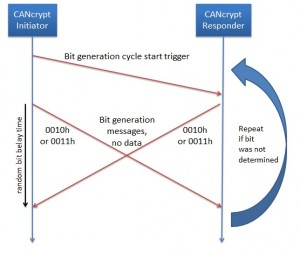
Bit generation cycle

Solely by monitoring CAN messages, one cannot identify the device that sent any individual message, because at that level, any device can transmit any message. As an example, let us allow two devices (named initiator and responder) to transmit messages with the CAN IDs 0010h and 0011h (and data length zero) within a “bit select time window”. Each node shall then randomly choose and send one of the two messages at a random time within the time window.

At the end of the bit select time window, a trace recording will show one of the following scenarios:

  1. One or two messages of CAN ID 0010h
  2. One each of CAN ID 0010h and 0011h
  3. One or two messages of CAN ID 0011h

Let us have a closer look at case 2 – one each. If these are transmitted randomly within the bit response time window, then an observer has no way to identify which device sent which message. However, the devices themselves know it and use this information to derive a bit from it.

Unfortunately we cannot use case 1 and 3, so if those happen, both nodes need to recognize it and re-try, using another next bit select time window.

Note 1: If one device wants to enforce a specific bit to the other, it may generate a “flip bit” message at the end of the cycle to indicate to the other device that this bit needs to be flipped.

Note 2: A variation of this scheme is to not use a random delay, but instead ensure that both devices transmit their message immediately after the trigger message. Then both messages arbitrate the bus at the same time and in a trace recording we will always see 0010h followed by 0011h.

Potential attacks: As usual, a denial-of-service kind of attack is always possible. By injecting messages an attacker can break the cycle, the devices would not be able to exchange a key in the first place. If an attacker has full physical access (oscilloscope, transceiver), he can determine which node sent which message. However, there is still some effort required to recognize which bits were actually generated (as participating devices can change interpretation). Last but not least anything “random” is always an attack vector. The participating devices need a reasonably good random number generator.

Book announcement: Implementing Scalable CAN Security with CANcrypt

February 22nd, 2016 Comments off

Nuremberg, 22nd of February 2016: Embedded Systems Academy announces their new book “Implementing Scalable CAN Security with CANcrypt”. You can meet the authors at the Embedded World 2016 from February 23rd to 25th in hall 1, booth 620 – the booth of our partner PEAK-System.

The book covers authentication and encryption for CANopen and other Controller Area Network protocols and will be published in Q2/2016. The introduced CANcrypt system by ESAcademy adds multiple levels of security to CAN. CANcrypt supports the grouping of multiple devices and the encrypted and authenticated communication between them. The CANcrypt security layer sits between CAN driver and higher layers and is therefore independent of higher-layer protocols or applications used.

The required system resources are minimal compared to traditional cryptography methods and can be scaled to the application’s security requirements. A key hierarchy enables implementing of smart, simplified key management that supports manufacturers, system builders/integrators and owners.

Demo and example code will be published using the BSD license.
For more information see www.cancrypt.net

Misc News as of February 2016

February 15th, 2016 Comments off

It is a busy start into 2016 with several new products and the Embedded World 2016 coming up next week.

New product – CANopen Logxaminer
Last year, we spent a lot of time helping clients to evaluate long CAN trace recordings and searching for misbehaviour of CANopen devices as well as manually generating statistics about such behaviour. In order to simplify such trace evaluations we wrote a dedicated utility that evaluates CANopen trace recordings. It supports common file formats used by recording tools from PEAK, Vector and ESAcademy.

For more information about the CANopen Logxaminer, follow the link.

New book about CAN security
Within Q2/2016 we will publish a new book, this time about CAN security. Recent publicized hacks show that CAN/CANopen are quite vulnerable, once an intruder/attacker has access to the network. Our new book introduces a scalable method that addresses both authentication and encryption, is independent of the protocol used and free sample code will be provided. A more detailed announcement will be published in our blog at www.esacademy.com/blog next week.

New 2016 price list
Our new 2016 price list is now valid, for current prices visit our CANopen online stores in Europe or USA. Prices have been lowered for the low-level entry version of our CANopen Magic tool as well as for the CANopen Magic high-end version including DLL access for custom test tool developments.

Next week’s Embedded World 2016
This years show in Nuremberg from February 23rd to 25th has almost 1000 exhibitors. For a complete list see
www.embedded-world.de/en/ausstellerprodukte/exhibitorlist

You can meet Chris or me (Olaf) from ESAcademy at the PEAK system booth. Hall 1, booth 620.

If you can not make it to the show and are still interested in selected news and updates, follow Olaf at twitter.com/ESA_Olaf or re-visit our blog after the show for a summary of impressions.

Looking forward to seeing some of you in Nuremberg

Olaf Pfeiffer

Impressions from the international CAN Conference iCC 2015

October 28th, 2015 Comments off

The 15th international CAN Conference took place in Vienna on October 27th and 28th 2015. On two days, a total of 23 papers were presented. Topics included current application examples, security and IoT (Internet of Things)  issues and “everything” CAN FD (Flexible Data Rate) related. CAN FD with its increased data rate was the major topic of this conference, many papers were directly related to it.

As CAN FD is not backward compatible to CAN, one of the session topics was migration from CAN to CAN FD. Mixing CAN and CAN FD controllers is only possible if the CAN FD messages are hidden from the CAN controllers as they would generate error frames upon reception. One approach is using partial networking transceivers where traditional CAN controllers are put to sleep during CAN FD communication. After seeing a specific sleep message, transceivers for partial networking can keep the connected CAN controller in sleep mode until a specific wake up message is received – no other message on the network causes a wake-up.

NXP presented a paper about their “FD Shield” transceiver. This transceiver is used to connect legacy CAN controllers to a CAN FD network. The CAN FD traffic is somewhat “shielded” from the CAN controller, only regular CAN traffic passes through but CAN FD messages are blocked as soon as they can be detected. However, there is a side effect: Each CAN FD frame on the network causes a local, not propagated receive error at the CAN controller side. As a result the CAN controller may go error passive. However, as transmits works fine, it will not go bus off and can still be used. Although not perfect, this is a quick and easy solution during a migration phase from CAN to CAN FD.

Another way to quickly connect to CAN FD networks is using Microchips external CAN FD controller using an SPI connection to the host controller. Here designers need to carefully choose the clock rate used on the serial interface side; depending on the CAN FD data rate used the SPI clock might need to be 10 or even 16Mhz. If a CAN FD data rate of 8Mbps is used, then a 10Mhz clock rate on the SPI side is sufficient to handle 100% bus load. However, the host controller of course needs to be able to handle the 10Mhz SPI traffic, too.

Other papers showed how CAN FD can be used in Linux systems, AUTOSAR and J1939, In general, the physical layout for CAN FD networks is not as flexible as it is with regular CAN. With faster bit rates ringing and reflections become more of a problem as they used to be. As usual, if an application tries to get close to the physical limits that a technology provides, more care must be taken when determining the physical layout and terminations.

With more and more CAN networks also getting some “remote access” option or even a gateway/firewall to the Internet, security of CAN networks suddenly becomes more important. In the past, CAN networks could be regarded as “closed” (inside a machinery, no remote access) so no precautions were taken in regards to security. Once a CAN network goes “online”, even if it is by the means of some firewall and even if it is only part-time, the entire security concept needs to be re-evaluated. Recent car hacks have shown that once hackers are past the firewall, they can do “anything” because there is no security layer in the CAN network.

Papers from Robert Bosch GmbH and the CiA showed some possible options to add encryption also to CAN communication, however, that directly has an impact on debugging and testing. If communication between two ECUs is secure, how do we monitor or debug it? So the debugger/tester/logger needs to part of this equation, too. It will be interesting to see where this goes, will at some point security be added to all CAN communication or will it be limit to “relevant” transmissions like commands that actually do something to the system?

Once the papers are added to the CiA’s server system, they will be available for download.

Categories: CAN, CANopen Tags: , ,

Free CANopen Configuration and Test Utility

October 27th, 2015 Comments off

At today’s 15th international CAN conference Olaf Pfeiffer of Embedded Systems Academy presented a paper about testing of highly dynamic CANopen systems. Such systems support plug-and-play and node ID assignment by LSS (Layer Setting Services, node ID gets assigned through the network). As a result, devices may change their node ID, making tests more challenging.

One of the test utilities introduced in this paper is now available as free download from ESAcademy’s web pages. It supports the extended concise DCF (Device Configuration File) as introduced in the paper. It allows you to easily write down configuration or test sequences in a table (save as .csv) and execute them using the free CANopen File Player.

The file format, the concise Default Configuration File is part of the basic CANopen definitions and has been in use for quite some time. The extension to it is simply a definition of a set of commands introducing the option to control things like addressing specific devices (identify by CANopen Identity record 1018h) and time delays / timeouts or user interactions.

In addition, the utility can re-play previously made CAN trace recordings, supporting a wide variety of formats from Vector, PEAK and others.

For more information on the format of the extended CDCF see the manual or download the free utility.

Impressions from the Embedded World 2015

March 2nd, 2015 Comments off

With about 900 exhibitors the Embedded World reached a size where it is impossible to “see it all”. Yes, you can still walk by all booths in a day, but you might easily miss hidden highlights. It was quite obvious that IoT – the Internet of Things – is a current hype. To me this is quite astonishing as already some 10+ years ago we built an “Embedded Internet Demo” – at that time based on a Philips 8051 with a dial-up modem connected. The main difference between now and then is that now smart phones are widely spread and we are “always online” and now can access our embedded devices “at any time”. Among the visitors one could recognize a lot of skepticism for what exactly we really need the IoT, other then it being hip and cool to be able to control “everything” with our smart phone.

An unusual approach to get remote access to embedded applications was shown by Raisonance (http://www.iotize.com) – they have a miniature NFC or Bluetooth module that connect to the JTAG/SWD debug port of an application. So it can be added to any application with debug port, sometimes even without the need to re-compile the code, if you have the knowledge where in memory the variables are that you want to have remote access to. A great tool to get started with IoT without requiring a re-design of existing hardware.

At the CiA (CAN in Automation) booth a CAN FD demo integrated devices and tools from multiple vendors. CAN FD (Flexible Data) allows higher bit rates and longer contents (up to 64 bytes) of the data frame. Especially bootloader applications and other software update features benefit from the higher data throughput. For such applications it seems to be possible to increase the effective data throughout 8 fold easily, potentially even more.

We at ESAcademy further enhanced our portfolio of CANopen Diag products. There is now a second hardware, based on PEAK’s mini Display, that offers a subset of the diagnostic features provided at a price point of well below 1000 Euro. The CANopen Test Machine System part of the CANopen Diag now allows to create tests based on MS Visio graphs. The transitions in a state diagram can be used to transmit or receive a CAN/CANopen message or to influence/set/test/query variables or timers. More details and examples will be published shortly.

Visit us at the Embedded World 2015 in Nuremberg

February 16th, 2015 Comments off

This year the Embedded World (www.embedded-world.de) in Nuremberg expects 30k+ vistors from 35+ countries. Show days are from 24th to 26th of February. For companies “into CAN” one of the hot topics is CAN FD – more and more products (microcontrollers as well as interfaces) are now available supporting the new standard supporting higher data rates. You can see the Bosch CAN FD demonstrator at the CiA booth (booth 608 in hall 1). This demo includes our CANopen Magic software connected to a CAN FD bus using the latest PEAK CAN interface. If you have questions and would like to meet us, come over to our partner PEAK System (booth 606, hall 1, just next to the CiA booth). Looking forward to seeing you!

Micro CANopen update, latest conformance test

December 17th, 2013 Comments off

ESAcademy recently released an update for its Micro CANopen source code software including an update to the CANopen Architect EDS editor and code generator. This update includes changes that were made to pass the latest Version 1.0.1 of the official CANopen conformance test by the CiA. The changes required mainly consisted of adapting SDO abort codes to the required values. For further changes, please refer to the release notes of the individual products. Customers with ongoing support service may download the latest versions from www.esacademy.org

Micro CANopen Source Code V6.11 released

May 10th, 2013 Comments off

Today we released a new version of our Micro CANopen source code. Updates and changes made include requirements from the latest CANopen conformance test as well as updates to the CiA 447 specific examples. Besides two bug fixes, the changes are:

Device switch themselves automatically to pre-operational when they detect a loss of a heartbeat that they are consuming. In the past this was application code specific, but as the conformance test requires it, we moved this function into the stack. In CiA 447 this is only done for the loss of the gateway’s heartbeat. Reaction to other heartbeat losses remains application code specific.

For CiA 447 devices, the shut down sequence is now also initiated if a gateway is not present. As before, devices wait for the next wake-up message before they try to communicate again.

Micro CANopen customers with a current maintenance and support contract may download this latest version from our servers as described on the delivery note for each product.

Potential risk warning for CiA 443 sub-sea systems supporting a bit rate change via Layer Setting Services

April 22nd, 2013 Comments off

Although ESAcademy is not an active member of the CiA 443 group, we have several customers and business partners using CiA 443 and came across a potential reliability issue in regards to bit rate changes.

It is our understanding that the reliability requirements for CiA 443 sub-sea applications are very high. Bootloaders are written and tested in a way that even power failures at any time or severe communication errors can not break the system. In worst case, an application is not programmed and a device remains in bootloader mode and is simply re-programmed again.

However, allowing the CAN bit rate to change with the currently specified mechanisms bears the risk of one or multiple devices failing. If in a CAN network devices are not configured to use the same bit rate, communication fails at a very low level. Devices will recognize that there are errors on the bus and potentially take themselves offline (bus off). If the devices are configured to use these different bit rates, then this error state can not be resolved.

How could such a situation occur?

The Layer Setting Services (LSS, see CiA 305) allow the setup of a bit rate, if all devices connected to a network support these services. Although the method of when exactly to do the bit rate change is very well specified and synchronized, the actual storing of this information (nodes copying this information to their local non-volatile memory) is not. It happens “one-by-one” and as no timings specified, this could be within seconds or even minutes. If there are severe bus communication errors during this time or even a power failure, then all devices will not have the same bit rate configured.

Possible solutions:

1.) Do not use switching of CAN bit rates by LSS, only use it for node ID assignments

2.) Use a power-on default bit rate. Any change to the bit rates is not stored in non-volatile memory, it is only temporary. With each reset or power cycle all devices fall back to their initial default bit rate.

3.) Use auto detect. Note: this only works if not all nodes are doing it, there must be at least one node communicating for the others to be able to do an auto detection. This feature is not available with all CAN controllers (requires passive listen-only mode).

4.) Check with CiA 305 group what else can be done to make the bit rate switch safer, for example by not only synchronizing the time of the physical switch, but also the time when this information is stored into non-volatile memory.

Until this is solved we recommend all existing systems to not make use of the bit rate switching by LSS.

Categories: CANopen Tags: , , ,