RSS Feed

Embedded Systems Blog

CANcrypt Update: Better Security and CANopen FD support, shown at Embedded World 2018

February 20th, 2018 Comments off

Today, EmSA released a software update for both the freely downloadable and the commercial version of CANcrypt. The update implements multiple recommendations from a security assessment.

As part of the NXP secure bootloader project, the experts at MathEmbedded did a security assessment of CANcrypt. The 43-page report examined possible attack vectors and potential weaknesses. Even to the original release the report stated: “We have not identified a straightforward attack that would allow an unauthorized attacker to easily accomplish all the steps [above].” But the latest update now fixes the discovered weaknesses or adds security notes and comments for application-specific configurations that need less security.

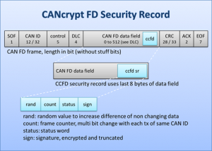
Just in time for the Embedded World 2018 in Nuremberg we can now show a first CANcrypt adaptation to CANopen FD. As CANopen FD already provides a direct, flexible communication method with USDO (Universal Service Data Object) supporting both broadcast and point-to-point communication, the easiest way to port the CANcrypt control messages to CANopen FD is to turn them into CANopen FD objects in the Object Dictionary. The CANcrypt control messages thus are “tunneled” through CANopen using dedicated Objects and USDO services. This allows implementing the CANcrypt grouping mechanism (similar to pairing, but for multiple devices). Authenticated messages are then exchanged based on a dynamically changing key. Each data transfer includes a random value that is used to continuously update the dynamic key.

Visit the CiA (CAN in Automation) at the Embedded World 2018 (hall 1, booth 1-630) to see the CANopen FD demonstrator and to learn more about CANcrypt. To download the free evaluation software or learn more about CANcrypt, visit our web pages for download and CANcrypt.net.

A security #Meltdown, also for embedded systems?

January 10th, 2018 Comments off

Meltdown and Spectre are considered by many to be the biggest security flaws in the history of computing, both in terms of numbers of affected devices (billions) and time they have been laying dormant (20 years). Whenever security issues like these that affect PCs and mobile devices become public, we take a look at how they might affect Embedded Systems as well. An inconvenient truth in our industry is that software in Embedded Systems does not get updated, to put it mildly, as often as regular desktop PCs. Sometimes that means “never”. That is why even “ancient” attack vectors like the WannaCry and its descendants such as Petya and NotPetya ramsomware can still cause major damage in various systems, even months or years after the underlying security issues have been made public.

The core issue behind Meltdown and Spectre is that parts of a memory protection and isolation system are being compromised on a hardware level. Such isolation is meant to ensure that one task or program can not access the memory used by another task or program and potentially spy out sensitive information. The “good news” for most older chips and many embedded microcontroller devices first: They often don’t have a vulnerable memory isolation logic (involving out-of-order or speculative code execution) in the first place. It is actually worse: The memory in most lower-end embedded chips is wide open to all running tasks. While some microcontrollers do provide an MPU (Memory Protection Unit, see ARM Community for an example), it is often limited in terms of number of memory areas, sizes and number of levels/tasks supported. From our experience it is safe to say that a large number of embedded applications doesn’t make use of it at all. And when an MPU is used, then the primary goal is often to protect code against memory-crossing bugs to make it safer against failure, but not attacks. With these types of systems, once a hacker manages to execute some code on an embedded device, this code should be assumed to immediately have access to all resources of the chip, including the memory.

This looks like a devastating assessment from a security standpoint, however, injecting code into an embedded microcontroller is not easy. Many such systems do not use an operating system at all, have no command line or only a very limited user interface without the option to load and start a piece of code. Typically the only way to inject code is through a bootloader or a debug interface, if at all. It is up to the system designers, sometimes the factory programming and the program running on an embedded microcontroller to disable casual access to these functions.

We know that for many designers of embedded systems, the time they can spend on security issues is limited. If you are part of this group, you may use the publicity around Meltdown and Spectre to justify some extra time to review potentially vulnerabilities to attacks that are based on the same principle: to load or inject malicious code that spies out or manipulates data in your embedded system.

For such a review, first look for all options how code could be injected into your system or altered. Could an attacker make use of any of the provided bootloader mechanisms or the debug interface? If you can’t disable all of these because you need to be able to update “legitimate” code, then authentication is mandatory and encryption during transmission highly recommended. Preferably implement different layers of authentication, for example one to access the interface to update code and another one to protect the code itself. For an example see the secure secondary bootloader we implemented for NXP. Also, review if your microcontroller has a MPU or similar and how you can make best use of it not only to protect the system from buggy code but also from intentional attacks.

CANopen Magic now supports CANopen FD

December 11th, 2017 Comments off

It was a lengthy process. Along with other experts we from Embedded Systems Academy participated in the CANopen FD definition group for more than 2 years now. Initially some only wanted a few changes. However as CAN FD is not backward compatible to CAN (classic CAN controllers produce error frames when they see a CAN FD message) the majority saw the chance to “dump complete backward compatibility” and add new and advanced features. The previous SDO communication (request-response scheme between one master and multiple devices) was replaced with the USDO communication – the Universal Service Data Object.

A first version of the definition of CANopen FD (CiA 1301) was released by the CiA in October this year. It is available from the CiA on request (www.can-cia.org/services/publications/). Some of the new features include:

  • TPDOs can now have up to 64 bytes of data (previous 8)
  • Full USDO mesh definition – every node can send client requests to every other node
  • USDO communication may be a broadcast to all nodes

The USDO service allows any device to send service requests to any other device, without the need for a master or manager to be involved. This greatly improves plug-and-play support and self-configuring systems, as now each device independently can analyse its surroundings: which devices are on this network and what kind of communication objects do they have available.

We at Embedded Systems Academy are now adding CANopen FD support to all our CANopen products. The first line of products supporting CANopen FD is our CANopen Magic software for the analysis and test of networks. As of the latest release (V9.0) all CANopen Magic products support both CANopen and CANopen FD. For CANopen FD an appropriate CAN FD interface must be connected. All of our current tests have been made with the PCAN-USB FD and PCAN-USB Pro FD interfaces from PEAK System.

We are currently in the process of contacting all current CANopen Magic users to inform them about their upgrade options. If you are using CANopen Magic and have not yet received an email from us about your upgrade options, please contact us.

CAN and CANopen FD at ‘sps ipc drives 2017’

November 6th, 2017 Comments off

Visit us in Nuremberg for the 28th international exhibition for Electric Automation, Systems and Components, the “sps ipc drives 2017”. The show is open from November 28th to 30th, 2017. Our software and solutions are shown on two displays at the NXP booth and the CiA (CAN in Automation) booth.

Our display at the NXP booth (Hall 10.1, Booth 325) focuses on CAN FD and security. The new features of CAN FD (bigger message frames, higher bit rate) are used to implement a more efficient and secure bootloader based on CANcrypt and AES based authentication and encryption. Join us for an informal lunch & learn session about CAN FD on Tuesday or Wednesday starting at noon (for about 45min) in the NXP on-site meeting room. Seats are limited, please register here to join.

Our display at the CiA booth (Hall 2, Booth 300) focuses on CANopen FD. A multi vendor demo setup shows one of the many new features available with CANopen FD: segmented broadcast. This transfer mode supports sharing data blocks (for example tables with data of drive acceleration ramps) instantly among multiple participants. In the demo, the data exchange is visualized using graphics, which are shared among multiple nodes.

Contact us, if you still need tickets for the event or if you would like to set an appointment to discuss your CAN FD / CANopen FD / CAN security requirements.

International CAN Conference (iCC) 2017 Videos Released

October 5th, 2017 Comments off

The CiA (CAN in Automation) user’s group released the presentation videos of the iCC 2017. Besides the keynote by Holger Zeltwanger there are three more presentations that we would like to highlight here in our blog:

Andrew Ayre and Olaf Pfeiffer (both ESAcademy): Automated trace analysis for testing of CANopen devices

This paper presents a summary of the debug information extractable from CANopen trace recordings. The functionality described in this paper are implemented in our Logxaminer software.


Olaf Pfeiffer (ESAcademy): Scalable security for CAN, CANopen, and other CAN protocols

This paper describes the main functionality of the CANcrypt security framework described in our book “Implementing Scalable CAN Security with CANcrypt”.


Bernhard Floeth (Opel) and Olaf Pfeiffer (ESAcademy): Using an enhanced condensed device configuration file format for CANopen boot-loading and/or device testing

This paper presents the enhanced CDCF player integrated in our free CANopen File Player and CANopen Diag projects. It supports spreadsheet based (.csv) Object Dictionary access with active flow control.


For a complete list of all available videos, go to: www.can-cia.org/services/conferences/icc

First Secure CANcrypt CAN FD Bootloader available

July 19th, 2017 Comments off

Today, the Embedded Systems Academy announces the availability of its secure CANcrypt CAN FD bootloader for the NXP LPC54618 microcontroller. The binary version is available as free download and may be used without limitations. For programming, the FlashMagic software (www.flashmagictool.com) and a PEAK PCAN-USB FD interface (www.peak-system.com) is required.

The security system is based on two symmetric keys, separating the code protection (happening at the manufacturer) from the download process done by a system integrator or service technician. The code file is AES-GCM (128-bit key) protected, offering both encryption and authentication. The local CAN FD connection (between service host and bootloader) is CANcrypt protected (128-bit key, authentication and partial encryption).

On the host side, the update process is fully integrated into the existing FlashMagic software that handles Flash programming for all NXP LPC microcontroller families.

Secure Bootloader Components

The figure illustrates the components of the system. The bootloader and the initial two keys (code protection, connection) are programmed into the LPC54618 device in a trustworthy manufacturer environment.

For a code update, the manufacturer creates a secure update file based on the first, code protection key. The file is encrypted and can be passed to the service technician through an unsecured channel such as email or web download. FlashMagic includes a minimal CANcrypt configurator, allowing the technician to initiate the code update using the second, CANcrypt connection key.

The secure bootloader does not by default disable the on-chip bootloaders and debug access by SWD to ensure that the default implementation can not accidentally lock a device. However, if all of these recovery methods are disabled, either during production or through a programmed application, then the secure bootloader remains the only method for code updates. In this configuration, once the CANcrypt connection key is lost, no further updates will ever be possible.

In addition to this free binary loader, ESAcademy offers a commercial version including all sources. This version offers more configuration options, such as customizing the CAN-FD bit rates (default is 500kbps/2000kbps) and security methods.

The security experts at MathEmbedded are in the process of reviewing the project. Once completed, we will publish the results here.

Download link: LPC54618_secure_CANFD_bootloader_V100.zip

MD5: 28a896e17a9a57b938337095fbd35372
SHA256: eb6d22e9390e0d1a79f04a81f926bcd98d496dd65f03535298e1ebf050e4729c

Secure CANcrypt CAN FD Bootloader for NXP LPC546xx

June 15th, 2017 Comments off

Together with NXP, the Embedded Systems Academy implements a secure CAN FD bootloader based on the CANcrypt security protocols. The bootloader will be available to users of the LPC546xx as free download. It is a “secondary bootloader”, meaning that it only provides security for the added bootloading channel, in this case the CAN FD interface. Someone with physical access to the LPC546xx will always be able to use the primary, on-chip bootloader to re-flash the device with any code.

The security system of the bootloader uses two security levels, each based on a symmetric key (default 128bit, up to 1024bit optional).

  1. On the CAN FD communication level, the CANcrypt protocol (www.cancrypt.eu) is used to ensure that only an authorized communication partner can activate the bootloader, erase the flash memory and send new code to the LPC546xx. The CANcrypt connection key used for this level is generated by the system builder or integrator that initially assembles the entire system.
  2. On the file transfer level, the file containing the new code to be loaded is encrypted using an encryption and authentication method based on a code protection key that gets programmed into the LPC546xx at the same time when the bootloader is installed (typically at manufacturer end-of-line assembly and test).
Secure bootloader security levels

Figure: Secure bootloader security levels

These two levels ensure a separation of the security features between manufacturer and system integrator/builder or service technician. Only an authorized technician will be able to connect his diagnostic device or software to the bootloader. But at this security level alone it will not be possible to generate authorized firmware, that requires an additional key only known to the manufacturer.

If you want to learn more about this bootloader, register now for the webinar (Thursday, June 29, 5:00 PM – 6:00 PM CEST) on the NXP website at: http://www.nxp.com/support/training-events/online-academy/lpc54000-series-online-training:LPC54000-Series-Online-Training

The version for free download is a binary only and will use a pre-selected cipher algorithms, fixed default configuration for parameters like CAN FD bit rates, CAN IDs and timings and timeouts used. The full source code is available from Embedded Systems Academy, giving users full control over all configurations and cipher algorithms used.

Could Ransomware Go Embedded?

May 23rd, 2017 Comments off

Could Ransomware Go Embedded?

For criminal hackers, ransomware has become increasingly popular. Ransomware locks a PC or encrypts its data and ask for a ransom to be paid to the hackers to unlock the PC or decrypt the data.

To which extent are embedded systems vulnerable to similar attacks? How realistic is it that firmware update mechanisms are used by hackers to install foreign code? Although loading malicious code to deeply embedded systems might seem far-fetched, some of the Snowden documents have shown that this already happened to the firmware in disk drives. Also, the well-documented Jeep Cherokee attack in 2015 that allowed a remote operator to almost entirely remote control the vehicle shook the industry. A wake-up call?

The Challenges

For hackers, the challenging part is that even though there has been a development to use more off-the-shelf hardware reference designs and software, most Embedded Systems platforms are still different from each other. Different microcontrollers require different code, so that ransomware has to be tailor-made for a specific microcontroller. The bootloader mechanisms in place are also different which means hackers need to find exploits for every one they are trying to attack.

A hacker’s task would be to write an exploit that manages to replace the entire original code and includes an own, password-protected, bootloader. With payment of the ransom, the hacker would share details on how to use his bootloader. There would of course always be the risk that this feature was not tested well enough by the hacker and a restore was not possible at all. It can be assumed that far more effort would have gone into generating the exploit and replacement code than the unlocking and restoring procedure.

Note that many microcontrollers have a built-in on-chip bootloader that cannot be erased or disabled, so if such a bootloader is usable in a device, a device with ransomware could be re-programmed on-site by the manufacturer or a technician. However, that might still be impractical or expensive if, for example, a very large number of devices were affected and/or the devices were at very remote locations.

A theoretical Example

To pick a specific application example, let’s have a look at an elevator / lift system: It consists of multiple microcontroller systems that are interconnected for example by CAN or CANopen and let us further assume they also feature a CAN/CANopen based bootloader mechanism.

A hacker installing ransomware replacing the existing bootloader with their own would need to

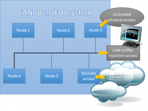
  1. get access to the system (either physical by installing a sniffer or remotely through a hacked PC that is connected to the system)
  2. know which microcontrollers are used
  3. know how the CAN/CANopen bootloader mechanism works (with some CANopen profiles, some details about it are standardized)

This information might be stored on multiple PCs: with the manufacturers, distributors, technicians or operators of the system. If one or multiple of those get hacked, an attacker might have all this information readily available. Note that the risk of a rogue or disgruntled employee with inside knowledge is often underestimated. The information above will typically be accessible by many people.

With this information, a hacker would be able to generate and load his own ransomware loader replacing the original code in all devices, which would disable the system. Now buttons, displays and controls would all stop working and every affected device / microcontroller would require a restore of its original firmware. If the affected devices still have an on-chip bootloader and if it can be activated, then a technician could manually update all affected devices. For large elevator systems with 20 or more floors and multiple shafts this task alone could take days.

How likely is such an attack?

The sophistication level required for the attack described above is quite high. Not only does it require “traditional” hacker knowledge but also in-depth knowledge of embedded systems. At this time it might be unattractive to most hackers as there are possibly still many “easier” targets out there. However, with enough resources thrown at the task, a determined hacker group could achieve the tasks listed above.

What are possible counter measures?

The most basic pre-requisite for an attack as described here is the knowledge about the specific microcontroller and bootloader mechanism used. This information can be obtained by either monitoring/tracing the CAN/CANopen communication during the firmware update process or by access to a computer that has this information stored. Protecting these in the first place has the highest priority.

The designer has to make sure that the firmware update process is not easy to reengineer just by monitoring the CAN/CANopen communication of a firmware update procedure. Things that we can often learn just by monitoring a firmware reprogramming cycle:

  1. How is the bootloader activated? Often the activation happens through a specific read/write sequence.
    Counter measure: Only allow authorized partners to activate the bootloader, best by using encryption such as CANcrypt or at least a challenge/response mechanism that is not repetitive.
  2. What file format is used? “.hex” or binary versions of it can easily be recognized.
    Counter measure: Use encryption or authentication methods to prohibit that “any” code can be loaded by your own bootloader.
  3. What CRC is used? Often a standard-CRC stored at end of the file or loadable memory.
    Counter measure: If file format doesn’t use encryption, at least encrypt the CRC or better use a cryptographic hash function instead of a plain CRC.

These counter measures are fall-back safeguards to protect the system if a higher security level has failed before. A hacker should not get bootloader access to a deeply embedded system in the first place. Ensure that all remote-access options to the bootloader level are well-secured.

News from iCC17 & EW17, CANcrypt released

March 20th, 2017 Comments off

The last two weeks were very exciting for us: We held several papers at the International CAN Conference and Embedded World (both in Nuremberg, Germany), participated in the first CANopen FD demonstrator at both events – with the new NXP LPC54618 – and finally released our book “Implementing scalable CAN security with CANcrypt”.

The CANopen FD demonstrator at the CiA (CAN in Automation) booth showed one of the new features of CANopen FD: segmented broadcast of larger data blocks with “Universal Service Data Objects” (USDOs). This feature can be used to broadcast images, configuration tables or even firmware updates. Here, any participant could be commanded to broadcast an image to all other participants. Such use cases were almost unthinkable with classic CANopen communication.

At Embedded World, PHYTEC showed a Nano Dimension 3D printer for PCBs. Prototyping your printed circuit boards just became a lot easier and faster. The circuits are printed with a highly conductive ink. It looks like the machine can directly produce boards from Gerber files.

At the NXP booth, one of the demos featured the NXP LPC54618 microcontroller with two CAN FD interfaces. The “FD” (Flexible Data rate) allows the data portion of a CAN message to be transmitted at higher bit rates. So far, classical CAN was limited to 1 Mbps. With currently available transceivers the data rate can now be up to 5 Mbps. Also in CAN FD, the maximum payload for each message is 64 bytes compared to eight bytes in traditional CAN. The demo compared different firmware download speeds. Using CAN FD, updates can now be transferred multiple times faster than before.

The release of our book about CANcrypt (www.cancrypt.net) stirred a lot of interest and we had many engaged discussions, also with some security experts. CANcrypt is a security framework and the security level actually used is configurable. As usually, there is a trade-off: the more security you require, the more resources both in CPU time as well as in memory space you need. For a configuration on the upper end of security, proven encryption methods like AES-128 can be used. It will be interesting to see if the lower-end lightweight “Speck” cipher reaches adequate security levels, too.

A first potential weak spot in one of the initial published configurations (user section, where user’s are setting up their own security configuration) was already discovered and is currently improved. The encryption of the secure heartbeat accidentally used only limited parts of the shared dynamic key, reducing the effective key to 32-bit. However, CANcrypt supports key sizes of up to 1024-bit. The next release will use a demo where a larger key is applied properly.

To learn about our bounty program, stay tuned by joining our mailing list or following us on twitter . Within the next few weeks we will start such a program to encourage others to search for possible flaws in the CANcrypt implementation.

CANcrypt technical functionality

February 26th, 2016 Comments off

A summary of the technical features used by CANcrypt

By Olaf Pfeiffer, Embedded Systems Academy GmbH, 26th of February 2016

At the Embedded World 2016 in Nuremberg, Embedded Systems Academy GmbH announced their book “Implementing Scalable CAN Security with CANcrypt”. The corresponding CANcrypt demo code will be published using an open license. At the Embedded World we have seen a lot of interest in the technical details. For those who do not want to wait until the publication of the book this article summarizes the key technical features of CANcrypt (also see our CANcrypt.eu web page for more information).

Core Functionality of CANcrypt

CANcrypt provides the following services:

  • Pairing: dynamic generation of a random key that is only known by the paired devices; optionally, one device can enforce a preset key to the other.
    • generate and exchange keys
    • optional storing of keys in non-volatile memory for permanent pairing
    • support of a key hierarchy when multiple keys are stored
    • maintain dynamically changing key (pseudo one-time pad)
    • dynamic key updated using shared random bit
  • Grouping: multiple devices share a common dynamic key
    • originally assigned through pairing
    • maintain dynamically changing key (pseudo one-time pad)
    • dynamic key cyclically updated by all grouped devices
  • Safety communication: any secure communication uses a preamble message
    • messages received are only accepted and passed on to application if together with the preamble the authentication and decryption is verified successfully
    • preamble identifies message CAN ID, security features used, has a counter and a signature
    • secure messages must be received within 10ms after the preamble to be valid

CAN message IDs required:

  • one CAN ID for each participating device
  • used for preamble and control messages
  • a CAN ID pair used for the random bit generation cycle

Cipher methods used

CANcrypt keys are symmetrical and dynamic, they are continuously updated. From the dynamic key and a message counter a pseudo one-time pad is generated that is used for the simple, customizable encryption.

If the secure pairing is only active for two nodes, a random bit generation cycle is used continuously in the background to introduce new bits to the dynamic key. If multiple nodes are paired, then the dynamic key update information is sent via an encrypted message.

The system pairing process is started using a CANcrypt configurator device. This can be done by a system builder or integrator once the CAN system is installed. It must happen in a secure environment. The keys generated at that time are stored locally in the devices connected – there is no need to keep any further copy of this key outside the system, minimizing the effort placed on key management. The keys cannot be duplicated. If a new device is added (or one exchanged), all keys need to be erased and newly generated.

As stored keys in each device make up a hierarchy, we can guarantee that erasing and regenerating keys can only happen when the configurator used is logged-in to the system based on a key high enough in the hierarchy to allow erasing and re-paring.

Operating principle for random bit generation

Bit generation cycle

Solely by monitoring CAN messages, one cannot identify the device that sent any individual message, because at that level, any device can transmit any message. As an example, let us allow two devices (named initiator and responder) to transmit messages with the CAN IDs 0010h and 0011h (and data length zero) within a “bit select time window”. Each node shall then randomly choose and send one of the two messages at a random time within the time window.

At the end of the bit select time window, a trace recording will show one of the following scenarios:

  1. One or two messages of CAN ID 0010h
  2. One each of CAN ID 0010h and 0011h
  3. One or two messages of CAN ID 0011h

Let us have a closer look at case 2 – one each. If these are transmitted randomly within the bit response time window, then an observer has no way to identify which device sent which message. However, the devices themselves know it and use this information to derive a bit from it.

Unfortunately we cannot use case 1 and 3, so if those happen, both nodes need to recognize it and re-try, using another next bit select time window.

Note 1: If one device wants to enforce a specific bit to the other, it may generate a “flip bit” message at the end of the cycle to indicate to the other device that this bit needs to be flipped.

Note 2: A variation of this scheme is to not use a random delay, but instead ensure that both devices transmit their message immediately after the trigger message. Then both messages arbitrate the bus at the same time and in a trace recording we will always see 0010h followed by 0011h.

Potential attacks: As usual, a denial-of-service kind of attack is always possible. By injecting messages an attacker can break the cycle, the devices would not be able to exchange a key in the first place. If an attacker has full physical access (oscilloscope, transceiver), he can determine which node sent which message. However, there is still some effort required to recognize which bits were actually generated (as participating devices can change interpretation). Last but not least anything “random” is always an attack vector. The participating devices need a reasonably good random number generator.