Security column: Updates and Outlook 2018/2019
Over the past year, our authors Christian Keydel and Olaf Pfeiffer have published several security- related CAN articles in the CAN newsletter. It’s now time for an up-to-date summary, review and outlook.
How do we address security?
To analyze the application-specific attack scenarios, we can group systems with CAN-connected devices as follows:
- Private and locked:
Only trusted persons have physical access to CAN wires and devices. There are no gateways to other networks. - Remotely accessible:
The CAN bus is connected to one or multiple gateways to other networks. - Time-limited physical access:
An untrusted party can be expected to have physical access to the CAN bus and devices for a limited time. - Unlimited physical access:
An untrusted party can be expected to continuously have physical access to the system.
What measures should be taken?
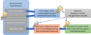
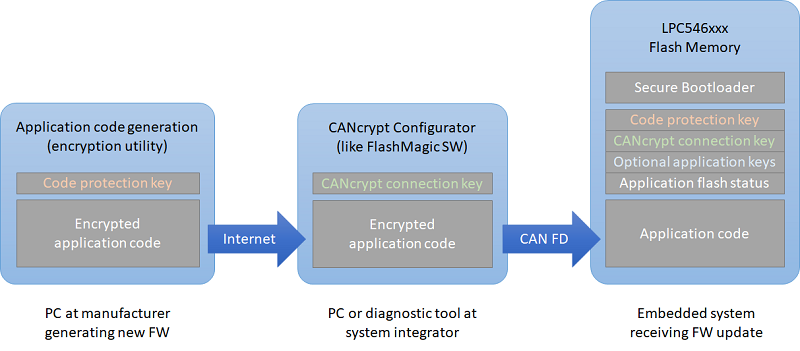
The recommended security measures for the mentioned groups range from none for group 1 to state-of-the-art for group 4 which presents the toughest challenge. With virtually unlimited physical access, an untrusted party can go as far as using flash/code extraction services for MCUs to obtain code and private keys. To thwart such attempts, you will have to use a secure microcontroller with built-in encrypted key and code storage like the NXP LPC54Sxx series for example. Here, the encryption is based on a private PUF (Physical Unclonable Function) which uses physical properties that vary for each chip and can never be extracted, like contents of uninitialized SRAM.
Securing CAN communications is a viable option especially for group 2 and in combination with physical protection also group 3 applications. As we’ve shown, it needs only minimal resources to implement injection monitoring in combination with a secure heartbeat (see article “Scalable CAN security”). However, due to the limited data size in CAN messages, individual message authentication often requires sending a second message with the authentication data.
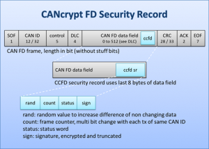
With CAN FD, adding security becomes easier, as the payload and security record can often be combined in a single CAN FD data frame, avoiding the overhead of managing a second authentication message.
What can we expect in the future?
In the new CiA CAN Cyber Security group it has become clear that where security is required, it should be added to all communication layers. To add message monitoring and flood protection to the CAN bus, there are hardware solutions like NXPs TJA115x secure CAN/CAN FD transceiver family. Similar protection can be added in software to the lowest driver layers. Just above the data link layer, CANcrypt (FD) provides a secure grouping mechanism. For the CANopen/CANopen FD and J1939 protocol layers, different security features can be implemented, including authenticated access for diagnostics or remote-control features.
Reaching highest security levels will only be possible if the hardware supports securing the software and communications, using built-in features for the protection of stored code and keys.
 Deutsch
 English


 Learn about our current product range for embedded systems


 Embedded Networking with CAN and CANopen. Your technology guide for implementing CANopen devices.
 Implementing scalable CAN security. Authentication and encryption for higher layer protocols, CAN and CAN-FD